

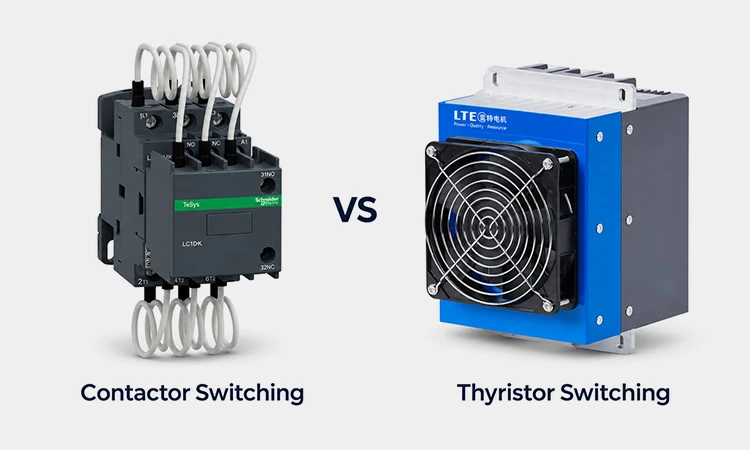
How quickly does your load's reactive power demand change? If it changes gradually, contactor switching is usually a good starting point. If it rises and falls quickly and repeatedly, consider thyristor switching, especially when your capacitor bank needs to respond within those short load cycles.
Before choosing either option, check two things: how quickly the complete capacitor bank needs to respond and whether your PFC controller output matches the switching device. If you're upgrading an existing panel, start with the controller model and the specifications for each capacitor step.
1. Contactor vs. Thyristor Switching at a Glance
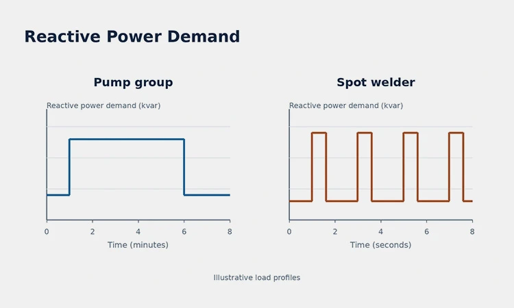
Start with how long each change in reactive power demand lasts and how often it repeats. A pump that runs for minutes at a time and a welder that draws power in short, repeated bursts can place very different demands on a capacitor bank.
| What to compare | Contactor switching | Thyristor switching |
| Typical load pattern | A starting point when changes in reactive power demand are gradual or sustained. | Worth evaluating when reactive power demand changes quickly and repeatedly. |
| Switching device | A capacitor-duty contactor connects or disconnects each capacitor step. | A solid-state thyristor module connects or disconnects each capacitor step. |
| PFC controller output | Typically uses a relay output. Check that the control circuit matches the contactor coil requirements. | Check that the controller output matches the thyristor module's control input. |
| Switching frequency and reconnection | Check the contactor's switching duty and how soon the capacitor step can be reconnected. | Check the module's switching duty and the conditions for reconnecting a capacitor step. |
| Panel design and maintenance | Allow for wear on the mechanical contacts. | Check the module's heat dissipation and cabinet ventilation requirements. |
Check the response of the complete capacitor bank. The time from a change in reactive power demand to a capacitor step coming online includes measurement, the controller's switching decision, and switching-device operation. If the same step needs to switch back on during a short load cycle, check its reconnection conditions as well.
2. How Does Each Switching Method Work?
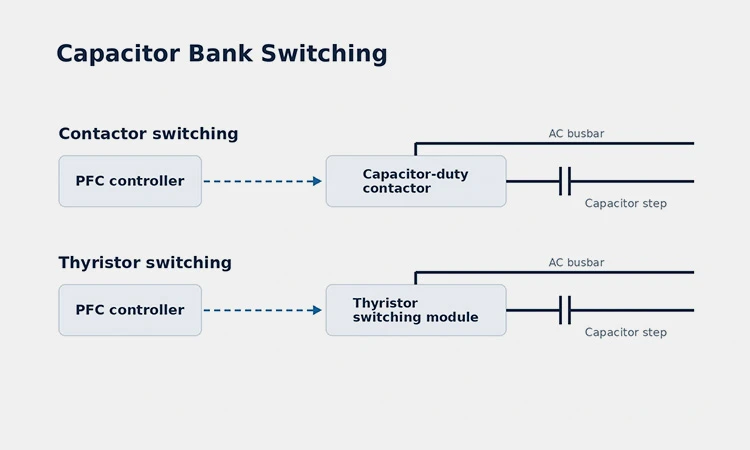
An automatic power factor correction (PFC) controller monitors the electrical load and decides when to add or remove a capacitor step. A step is a group of one or more capacitors that switch together. The controller sends the command, and the switching device connects or disconnects that step.
Contactor Switching
When the controller calls for another step, its output energizes the coil of a capacitor-duty contactor through the control circuit. The contactor's main contacts close, connecting the capacitor step to the supply. When the controller removes the command, the coil de-energizes and the main contacts open.
Thyristor Switching
When the controller calls for another step, it sends a control signal to the thyristor switching module. The module uses semiconductor devices to connect the capacitor step to the supply. This switching action takes place without moving contacts. The controller's output and the module's control input must be compatible.
3. Which Switching Method Fits Your Load?
Two facilities can have the same peak reactive power demand and still need different switching methods. What matters is how long the demand lasts and how often it changes. A capacitor step that has time to operate during a sustained change may be too slow to help during a short, repeated load cycle.
How Fast Does Your Reactive Power Demand Change?
If you have a power meter or power quality analyzer, look at the reactive power (kvar) trend during a representative production cycle. Check three things:
Magnitude. How large is each change in kvar? Compare it with the planned capacitor step sizes.
Duration. How long does the demand stay at the new level? This helps you judge how quickly the bank needs to respond.
Repetition. How often does the same change recur? If the bank needs to switch the same step back on, check its permitted reconnection time.
For short machine cycles, use a recording interval fine enough to show the individual changes. A trend averaged over several minutes can hide the peaks you need to evaluate.
Example 1 · A Pump Group With Sustained Load Changes
Imagine a pump group where a second pump starts as demand rises and then stays on for several minutes. If the kvar trend shows a sustained increase and the application allows enough time for the bank to respond, contactor switching is a reasonable starting point. Check whether the planned step sizes suit the change in demand and whether the expected switching frequency is within the contactor's rating.
Example 2 · A Spot Welder With Short, Repeated Load Cycles
Imagine a spot welder that draws reactive power in short bursts throughout production. If compensation is needed during those bursts, evaluate thyristor switching. Compare each burst duration with the response of the full capacitor bank, including the controller and switching module. Also check whether the same capacitor step can reconnect within the required cycle.
4. How Do You Match the PFC Controller to the Switch?
If you already have a PFC controller, start with its model number and wiring diagram. Check the output type and the number of independently controlled steps, then compare those details with the switching devices in your panel.
For Contactor-Switched Capacitor Banks
Check the contactor coil voltage and whether the controller's output is rated for the coil load in the proposed control circuit. Use the wiring diagrams to verify how the coil is powered and how the controller switches it.
View the PFC Controller for Contactors
For Thyristor-Switched Capacitor Banks
Check what signal the thyristor module expects at its control input. Compare the required signal type, voltage, and terminal connections with the controller's output specifications. If you're replacing contactors in an existing panel, use those two wiring diagrams to determine whether you can keep the current controller.
View the PFC Controller for Thyristor Switches
5. What Should You Check on the Capacitor Step?
If you're choosing a contactor or thyristor switch, start with the capacitor step it will operate. A step may contain one capacitor or several that switch together. The nameplate gives you the rating of one unit. The panel's step schedule or wiring diagram shows what the switch will actually connect.
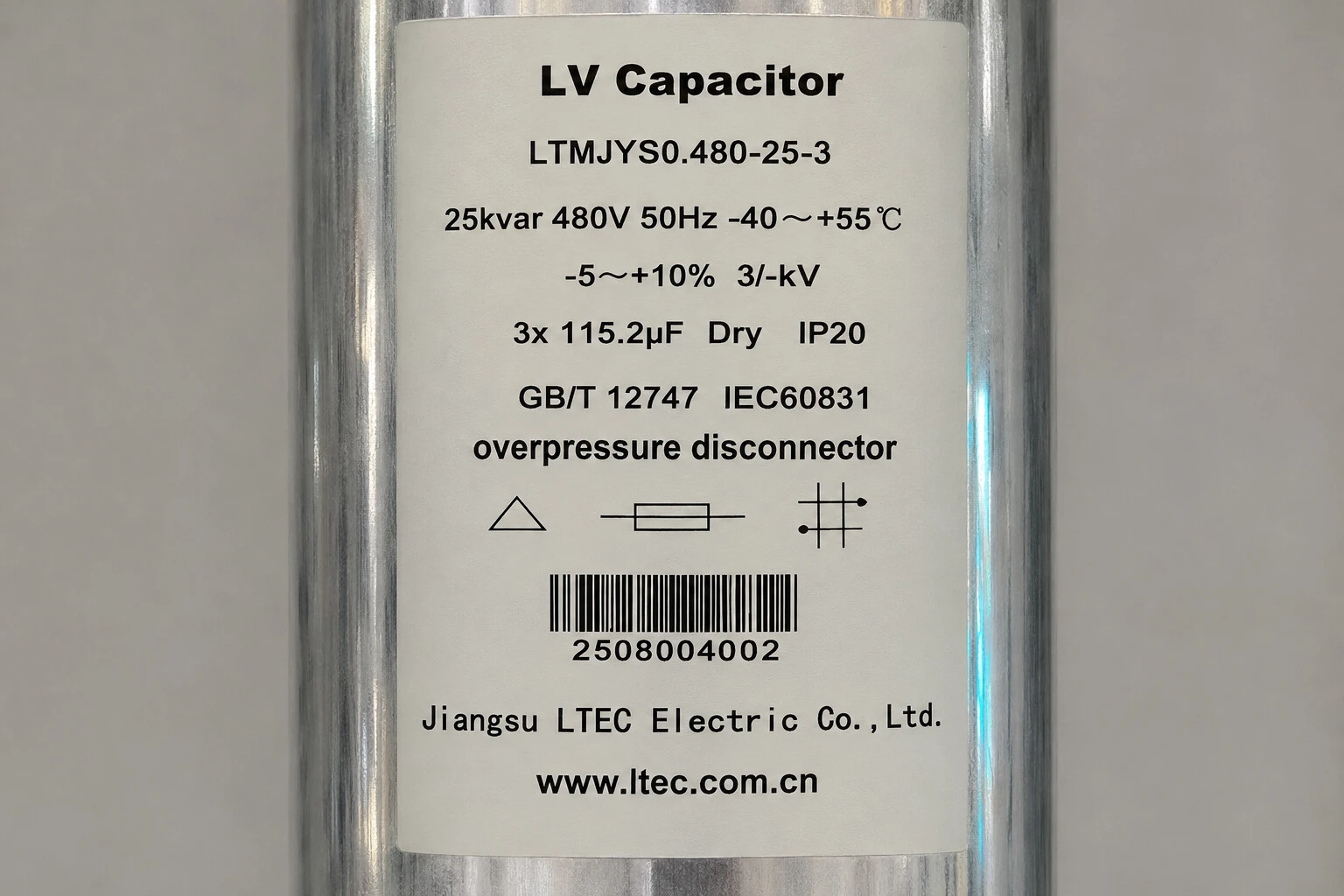
The capacitor shown below, model LTMJYS0.480-12.5-3, is rated at 12.5 kVAR at 480 V and 50 Hz. The triangle on its nameplate indicates a delta (Δ) connection.
Before selecting the switching device, check three details:
System voltage and frequency. Record the panel supply values alongside the capacitor's nameplate ratings. The 480 V in this example is the capacitor's rated voltage. Check the panel documentation for the supply voltage.
Capacitors per step. Confirm how many units switch together and check the current of the complete step against the switching device's rating for capacitor duty.
Detuned reactor. If the step includes a series reactor, check the ratings of the capacitor and reactor as a pair. A series reactor affects the voltage across the capacitor during operation.
6. What to Share Before Requesting a Quote
If you're specifying a new capacitor bank or upgrading an existing panel, share whatever you have from this list:
Supply voltage and frequency at the panel.
Total compensation capacity and step sizes, in kvar. For an existing panel, a step schedule or capacitor nameplate photo is a good starting point.
How the load changes during operation. A kvar trend is helpful. If you don't have one, describe which equipment starts and stops, how long it runs, and how often the cycle repeats.
Existing component details, if you're upgrading. Include the PFC controller and switching device model numbers, plus any detuned reactor fitted to the bank. A wiring diagram is helpful if available.
If you're still deciding between contactors and thyristor switches, start with your load pattern and panel details. These give us a basis for discussing which switching method fits your application and what to check before choosing a controller.
Frequently Asked Questions
1. Is Contactor Switching Suitable for a Capacitor Bank With Variable Loads?
Yes, if each change in reactive power demand lasts long enough for the capacitor bank to respond and the expected number of switching operations is within the contactor's rating. If your kVAR trend shows short, repeated peaks that need compensation during each cycle, evaluate thyristor switching.
2. How Fast Does a Thyristor-Switched Capacitor Bank Respond?
The response time depends on how quickly the controller detects a change, decides which capacitor step to switch, and sends the command. The thyristor module's switching time covers only part of that process. If the same step needs to switch on again soon after switching off, also check the system's reconnection delay.
3. Can I Reuse My PFC Controller When Upgrading From Contactors to Thyristor Switches?
You may be able to reuse it if its output signal matches the thyristor module's control input and its switching settings suit the required response and reconnection times. Compare the two model-specific wiring diagrams and manuals before deciding which components to keep.
4. Can I Use the Same Capacitors When Changing From Contactor to Thyristor Switching?
Possibly. Check the existing capacitors' nameplate ratings and how they are grouped into steps. Then verify that the new switch is rated for the complete step and that the capacitors meet the proposed system's reconnection requirements. If the step includes a detuned reactor, check the capacitor and reactor ratings together.
5. Do I Still Need a Detuned Reactor With Thyristor Switching?
It depends on the harmonic levels and resonance risk at your site. The thyristor switch controls when a capacitor step is connected. A detuned reactor helps limit harmonic amplification and protects the capacitors. Use the site's harmonic measurements and capacitor bank configuration to assess whether detuning is needed.