

Table of Contents
1.Power Factor Controller Selection Checklist
2.How Many Switching Steps Do You Need?
3.Does the Controller Match Your CT?
4.What Voltage Will the Controller Measure?
5.Will the Controller Output Match Your Switching Device?
6.How to Compare Controller Models
7.What to Share Before Requesting a Quote
8.Frequently Asked Questions
If you already have your capacitor bank specifications, start with four checks: how many steps must switch independently, what current the CT supplies on its secondary side, what voltage the controller will measure, and what output the switching device requires. You can usually find these details in the panel wiring diagram, capacitor step schedule, CT nameplate, and switching device datasheet.
Use those four checks to compare controller models. If you're replacing an existing controller, start with its model number and wiring diagram. Even when two controllers have the same step count, their CT inputs, voltage measurement connections, and switching outputs can differ.
1. Power Factor Controller Selection Checklist
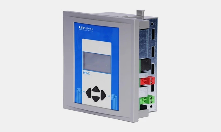
Put your panel wiring diagram, capacitor step schedule, and CT nameplate next to the candidate controller's manual. Use this checklist to compare what the panel requires with what the controller supports.
| What to check | Where to find it on your panel | What to verify in the controller manual |
| Number of switching steps | Use the step schedule or wiring diagram to count how many capacitor steps must switch independently. | Check how many outputs are available for capacitor switching. Count only the outputs that can control capacitor steps. |
| Current transformer (CT) input | Read the ratio and rated secondary current from the CT nameplate. Use the wiring diagram to identify which phase the CT measures. | Confirm that the controller accepts the CT's secondary current and supports the required ratio and measurement arrangement. |
| Measuring voltage | Trace the voltage measurement circuit on the wiring diagram. Identify whether it measures between two phases or between a phase and neutral. | Check the allowed measuring voltage range, frequency, and connection method. Also verify the controller's power supply requirements. |
| Switching output | Check the contactor coil specifications or the thyristor module's control input specifications. | Confirm that the controller's output type and electrical ratings match the control circuit shown in the wiring diagram. |
If you're replacing an existing controller, keep its exact model number handy. The model number helps you find the right manual, and the panel diagram shows which outputs you're actually using.
2. How Many Switching Steps Do You Need?
Count the capacitor groups that your controller must switch independently. Start with the panel's step schedule. If you only have a wiring diagram, look for the groups of capacitors that are switched together.
Count Steps From the Panel, Not From the Capacitor List
Suppose a panel has four capacitor units. Two units always switch together, and the other two switch independently. That gives you three switching steps:
| Step | Capacitor units switched together | Controller outputs needed |
| Step 1 | 2 | 1 |
| Step 2 | 1 | 1 |
| Step 3 | 1 | 1 |
| Total | 4 | 3 |
The panel's total kVAR tells you how much compensation it is designed to provide. The step schedule tells you how many separate switching commands the controller needs to send.
Check How Many Outputs Are Available for Capacitor Steps
In the controller manual, look for the number of capacitor-step outputs. Some controllers list an alarm contact separately, so check each terminal's function when comparing models. If you plan to add another independently switched step later, include it in your count.
3. Does the Controller Match Your CT?
Read the current transformer (CT) nameplate and check two things in the controller manual: the rated secondary current the controller accepts and how it handles the CT ratio. These are separate checks.
Match the Rated Secondary Current
A CT marked 400/5 A has a rated primary current of 400 A and a rated secondary current of 5 A. In this example, the controller must support a 5A CT input. If the nameplate reads 400/1 A, check for a 1A CT input instead. Some controller models support both, so verify the exact model you plan to use.
Check the Ratio Setting and Measurement Phase
Next, check how the controller manual asks you to enter the CT information. For a 400/5 A CT, the rated primary current is 400 A, and the ratio is 80:1. Use the value that corresponds to the setting shown in the manual.
If you're reusing an existing CT, use the panel wiring diagram to identify which phase it measures. Then check the new controller's wiring diagram for the required relationship between the CT phase and the voltage measurement connections.
4. What Voltage Will the Controller Measure?
Start with the panel wiring diagram. Find where the controller measures voltage and check whether the measurement is taken between two phases or between a phase and neutral. Then compare the voltage and frequency at those terminals with the range and connection options listed in the controller manual.
| Voltage to check | Where to verify it |
| Panel supply voltage | Check the panel's electrical specifications or single-line diagram. |
| Controller measuring voltage | Follow the measurement circuit on the wiring diagram and check the controller's permitted input range for that connection. |
| Controller power supply voltage | Check the controller's supply requirements. The model's wiring diagram shows whether the supply and measurement share a connection or use separate terminals. |
What Does the 480 V on a Capacitor Nameplate Tell You?
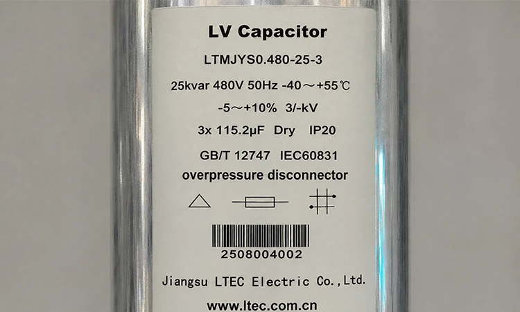
The capacitor in the photo is rated at 12.5 kVAR, 480 V, and 50 Hz. Those values describe the capacitor. To find the voltage the controller will measure, go back to the panel wiring diagram. This distinction matters in a detuned bank, where a series reactor can raise the voltage across the capacitor above the panel supply voltage.
5. Will the Controller Output Match Your Switching Device?
Start with the device that switches each capacitor step. Its datasheet tells you what the control circuit needs. The PFC controller manual tells you what each output can provide.
| Switching device | What to check on the device | What to verify in the controller manual |
| Capacitor-duty contactor | Coil voltage, whether the coil needs AC or DC, and the coil's electrical load. | For a relay output, check the contact rating for the proposed coil circuit. If the controller has dry contacts, use the wiring diagram to identify where the coil gets its control power. |
| Thyristor switching module | Required input signal type, signal voltage, and control terminals. | Check that the controller output matches the module's input requirements. Use both wiring diagrams to confirm how the interface is intended to connect. |
If you're replacing a controller, compare the full model numbers and the wiring diagrams for both devices. Two controllers can have the same number of steps and use different output types. For example, a relay contact and a transistor output have different electrical characteristics, so check the interface before choosing a replacement.
If you're still deciding which switching method suits your load, see Contactor vs. Thyristor Switching for Capacitor Banks.
6. How to Compare Controller Models
Once you have the panel specifications, compare each candidate controller against the same set of requirements. Use the manual for the exact model you plan to order. If a specification is missing, mark it as To confirm, so you know what to ask the supplier.
| What to compare | Your panel requires | Model A | Model B |
| Capacitor-step outputs | ___ independently switched steps | ___ | ___ |
| CT input | CT ratio _ / _ A, secondary rating ___ A | ___ | ___ |
| Voltage measurement | _ V at _ Hz, phase-to-phase or phase-to-neutral | ___ | ___ |
| Controller power supply | ___ V available at the controller supply terminals | ___ | ___ |
| Switching output | Contactor coil or thyristor module input requirements: ___ | ___ | ___ |
| Switching and reconnection delays | Required switching interval and minimum time before the same step can reconnect: ___ | ___ | ___ |
Check the timing settings before making your final choice.
A delay between switching different steps and the minimum time before reconnecting the same step answer different questions. Check how each controller defines its settings, then verify that they suit the panel's switching sequence and the capacitor step's reconnection requirements.
Compare controllers by switching type
- PFC Controller for Contactor-Switched Capacitor Banks
- PFC Controller for Thyristor-Switched Capacitor Banks
7. What to Share Before Requesting a Quote
If you'd like help selecting a PFC controller, send your panel wiring diagram and capacitor step schedule if you have them. For a replacement, include the make and full model number of the existing controller. If the drawings are unavailable, share what you have from this list:
- Capacitor steps:The number of independently switched steps and the kvar of each step, if known.
- CT details: A nameplate photo or the CT ratio and rated secondary current.
- Voltage details: The panel supply voltage and frequency, plus the controller's measuring and supply voltages if known.
- Switching device: The contactor or thyristor module model, with its coil or control input specifications if available.
A photo of the existing controller label and the CT nameplate is enough to start the conversation. Include any planned changes, such as adding a capacitor step or switching from contactors to thyristor modules.
Frequently Asked Questions
Q: 1. Does a 6-Step PFC Controller Control Six Individual Capacitors?
A: A 6-step PFC controller can control up to six independently switched capacitor groups. Each group can contain one capacitor or several that switch together. Use the panel's step schedule to count the groups that need separate commands.
Q: 2. How Do I Know Whether I Need a 1 A or 5 A CT Input?
A: Read the rated secondary current on the CT nameplate. A 400/5 A CT requires a controller that supports a 5 A input, while a 400/1 A CT requires support for 1 A. Some models accept both, so check the exact model's manual and follow its configuration instructions.
Q: 3. Can I Use the Capacitor Nameplate Voltage to Select the Controller?
A: Use the voltage at the controller's measuring terminals to check compatibility. For example, a capacitor marked 480 V has a rated voltage of 480 V. The panel wiring diagram shows which voltage the controller measures and how it is connected. Check the controller's power supply requirements separately.
Q: 4. Can I Replace My PFC Controller With Another Model That Has the Same Number of Steps?
A: Only if the replacement also matches the panel's CT input, voltage measurement connections, power supply, and switching outputs. Pay particular attention to the output interface if the panel uses thyristor modules. Compare the wiring diagrams for the exact models before ordering.
Q: 5. Which Switching Delay Settings Should I Check When Replacing a PFC Controller?
A: Look for the delay between step operations and the minimum time before the same step can reconnect. Check how the replacement controller defines each setting, then compare it with the panel's switching sequence and capacitor discharge requirements.