

You've already worked out that your capacitor bank needs 100 kVAR. How should you split it? Four 25 kVAR steps give you the same total capacity as a 12.5 + 12.5 + 25 + 50 kVAR layout. But if your panel needs only 12.5 kvar of correction during light-load operation, only the second layout has a step that matches that demand.
Start by estimating how much correction you need to reach your target power factor at light load and during normal operation. Then check which step combinations come close to those needs and whether your PFC controller supports the layout. This guide uses two 100 kVAR examples to show how to make that comparison.
1. How to Choose the Smallest Capacitor Step
Start with the smallest recurring amount of compensation needed to reach your target power factor. Look at a representative operating cycle that includes light load, normal production, and higher demand. The smallest step should be useful during the light-load periods when correction is actually needed.
Check What Your kvar Trend Represents
If an existing capacitor bank was running when the data was recorded, check where the meter was installed and which capacitor steps were on. A meter that sees both the loads and the bank shows the net reactive power after any active compensation. Use the readings together with the target power factor and the bank's operating status to determine how much correction is needed.
Test the First Step at Light Load
Suppose a panel regularly needs about 12.5 kvar of correction at light load. A 12.5 kvar step gives the controller a closer match than a 25 kvar step. With 25 kvar as the smallest available step, the controller may leave the bank off, or it may supply more correction than needed if that step is switched on. The actual decision depends on the controller's settings and switching logic.
Once you have a candidate for the smallest step, check how the remaining steps combine at normal operating loads. A suitably sized first step can still leave gaps higher up the range.
2. Equal vs. Unequal Capacitor Bank Steps
Two capacitor banks can have the same total kvar and the same number of switching steps while offering different compensation levels. The difference comes from how much kvar each step adds and which steps can be combined.
Compare Two 100 kVAR Layouts
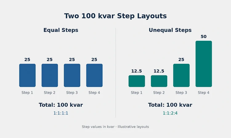
In this example, both banks have four independently switched steps. The values shown are the compensation each step provides under the same system conditions.
| Equal steps | Unequal steps | |
| Step sizes | 25 + 25 + 25 + 25 kvar | 12.5 + 12.5 + 25 + 50 kvar |
| Step size ratio | 1:1:1:1 | 1:1:2:4 |
| Smallest step | 25 kvar | 12.5 kvar |
| Theoretical compensation levels | 0, 25, 50, 75, and 100 kvar | 0 to 100 kvar in 12.5 kvar increments |
Test the Layout Against Your Usual Loads
Take a few compensation requirements from your operating data and compare them with the levels each layout can provide. Here are three illustrative demand points:
| Compensation needed | Equal steps | Unequal steps |
| 12.5 kvar | Nearest levels are 0 and 25 kvar | One 12.5 kvar step |
| 37.5 kvar | Nearest levels are 25 and 50 kvar | One 12.5 kvar step plus the 25 kvar step |
| 75 kvar | Three 25 kvar steps | The 25 and 50 kvar steps |
If your usual compensation needs fall close to the levels an equal-step bank offers, that layout may be sufficient. If they often fall between those levels, an unequal layout can give you a closer match.
Check for gaps beyond the smallest step. A bank with 12.5 + 25 + 62.5 kVAR also totals 100 kVAR and starts at 12.5 kVAR, but it has no combination that provides 50 kVAR. List the possible totals and check them against the loads you see most often. Then verify that your PFC controller supports the step sizes and can select the combinations you need.
3. Will Your PFC Controller Support the Step Layout?
Before finalizing your step sizes, open the manual for the exact PFC controller model you plan to use. Check how many outputs are available for capacitor steps and how the controller assigns a kvar value to each output.
For the 12.5 + 12.5 + 25 + 50 kvar example, you need four independently controlled outputs. If the controller uses relative step sizes, this layout is expressed as 1:1:2:4, with 12.5 kVAR as the base step. If the model uses automatic step detection, check what it can detect and which settings still need to be verified during commissioning.
Check How the Controller Moves Between Levels
The 1:1:2:4 ratio describes the size of each step. To see how the bank will move between compensation levels, check the controller's switching logic. For example, if the 50 kvar step is already on and the demand rises to 62.5 kvar, the bank can reach that level by adding an available 12.5 kvar step. Check how the controller selects that step and whether its switching and reconnection delays suit your load profile.
For a complete check of step outputs, CT input, measuring voltage, and switching interfaces, see How to Select a Power Factor Controller for a Capacitor Bank.
4. How to Check the Capacitor Rating for Each Step
Once you've chosen the kvar for each step, check how much compensation the selected components will deliver at your panel's operating voltage and frequency. Start with the capacitor nameplate, then check how the step is assembled.
Read the Capacitor Nameplate
The capacitor shown below, model LTMJYS0.480-12.5-3, is rated at 12.5 kvar at 480 V and 50 Hz. That rating applies to one unit under the conditions shown on its nameplate.
For example, two of these capacitors switched together in parallel at 480 V and 50 Hz, without a series reactor, would form one nominal 25 kvar step. If your panel operates at a different voltage or frequency, check the expected output at those conditions before entering the step value in your schedule.
Check the Complete Step If It Includes a Detuned Reactor
If the step includes a detuned reactor, verify the combined capacitor–reactor step rating at the panel supply voltage and frequency. The series reactor changes the voltage across the capacitor, so use the kvar specified for the complete assembly when comparing it with your planned step size.
5. What to Share for a Step Sizing Review
If you know the total kVAR your capacitor bank needs but are still deciding how to split it, send us your proposed step layout. If you haven't drafted one yet, share what you have from this list:
- Total compensation and target power factor. Include the panel supply voltage and frequency.
- Typical operating conditions. A kVAR trend covering light load and normal production is helpful. If a capacitor bank was already running when you recorded it, note where the readings were taken and which steps were on, if known.
- Step layout and controller. Include the planned number of steps, any proposed kvar values, and the PFC controller model if you've already chosen one.
- Existing components. If you plan to reuse capacitors or detuned reactors, include their nameplate photos or model numbers.
Even a rough step schedule gives us a starting point. We can use it to review whether the proposed compensation levels fit your usual loads and identify which capacitor and controller specifications to check next.
Frequently Asked Questions
1. Should All Capacitor Bank Steps Be the Same Size?
Equal steps work well when their available compensation levels are close to what your panel usually needs. If the required kvar often falls between those levels, compare an unequal-step layout to see whether it offers a closer match. Then check that your PFC controller supports the proposed layout.
2. How Small Should the First Capacitor Step Be?
Start with the smallest recurring amount of correction needed to reach your target power factor during light-load operation. If the panel regularly needs about 12.5 kvar of correction at light load, a 12.5 kvar step is a closer match than a 25 kvar step. Check that the controller can detect and switch a step of that size.
3. How Can I Check for Gaps Between Compensation Levels?
List the kVAR totals you can get by switching on individual steps and combining them. Compare those totals with the correction your panel commonly needs. For example, a 12.5 + 25 + 62.5 kVAR layout provides 100 kVAR at full output, but if you need 50 kVAR, the nearest available levels are 37.5 and 62.5 kVAR.
4. Can I Use Unequal Capacitor Steps With Any PFC Controller?
Check the manual for the exact model. Confirm that it has enough step outputs, can be configured for your proposed step sizes or ratios, and can select the combinations your application needs. For example, a four-output controller must also support 1:1:2:4 to use the four-step layout discussed in this article.
5. Is the Capacitor Nameplate kvar the Same as the kvar Delivered by a Detuned Step?
The nameplate lists the kvar of one capacitor at its rated voltage and frequency. If the step includes a detuned reactor, use the specified kvar of the complete capacitor–reactor assembly at the panel's operating voltage and frequency when preparing your step schedule.